Lab 5 - Linear PID and Linear Interpolation
Posted on 2026-03-14
Prelab: BLE Debugging Setup
For PID tuning I needed a way to adjust gains and collect data without re-uploading firmware each time. I added BLE commands to start/stop the PID controller, send back logged data, and update gains on the fly. A hard stop timer on the Artemis kills the motors after a set duration as a safety net.
ble.send_command(CMD.SET_PID_GAINS, f"{KP}|{KD}|{KI}")
ble.send_command(CMD.SET_SETPOINT, "304")
ble.send_command(CMD.SET_MAX_PWM, "120")
ble.send_command(CMD.START_PID, "")
time.sleep(6)
ble.send_command(CMD.SEND_PID_DATA, "")
The controller logs up to 1500 samples per run (timestamp, raw ToF, extrapolated distance, motor command). After it finishes I pull the data back and plot it in Jupyter.
I also wrote a sensor diagnostic that collects both ToF sensors for 5 seconds. This helped me discover my front and side sensors were swapped, which I fixed by pointing the PID loop at the correct sensor.
PID Control
I went with a PD controller. The task is position control with a fixed target so proportional handles steady-state fine, and derivative damps overshoot. No integrator needed since nothing is persistently pushing the car off the setpoint.
I started with P-only at Kp=0.05 and worked up:
| Config | Kp | Kd | Overshoot | Settling (<30mm) |
|---|---|---|---|---|
| P-only | 0.05 | 0 | 83mm | didn’t settle |
| P-only | 0.15 | 0 | 31mm | 0.84s |
| PD | 0.10 | 0.05 | 5mm | 0.50s |
The ToF gives distances 0-4000mm. With a setpoint of 304mm and Kp=0.10 the max PID output is about 170, clamped to MAX_PWM=120. Kd=0.05 was enough to cut overshoot from 31mm to 5mm. I tried Kd=0.5 first but the motor command just flipped back and forth between forward and reverse.
For the deadband I set a floor of 60 PWM (the minimum that moves the car, from Lab 4). Within ±15mm of the setpoint I set motors to 0 to prevent jitter.
Range and Sampling Time
I used Short distance mode on the VL53L1X for faster updates (~11 Hz). The PID loop runs at about 388 Hz, roughly 36x faster than the sensor.
Results
Final controller: Kp=0.10, Kd=0.05, MAX_PWM=120, Setpoint=304mm
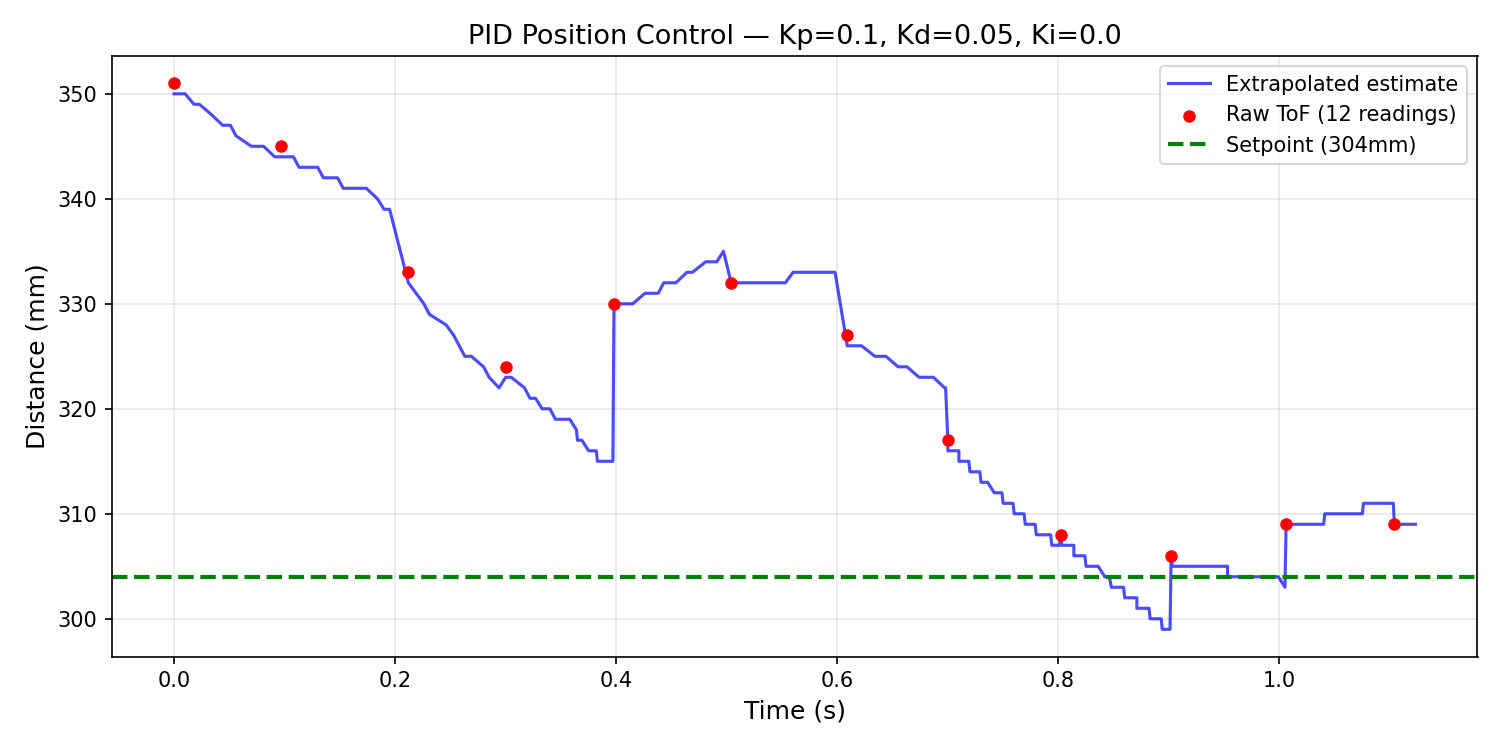
ToF distance over time. Blue is the extrapolated estimate, red dots are raw sensor readings, green is the setpoint.
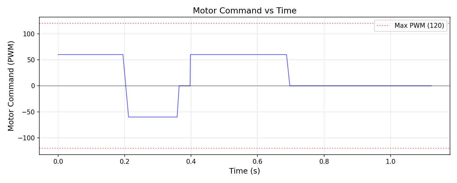
Motor PWM command over time.
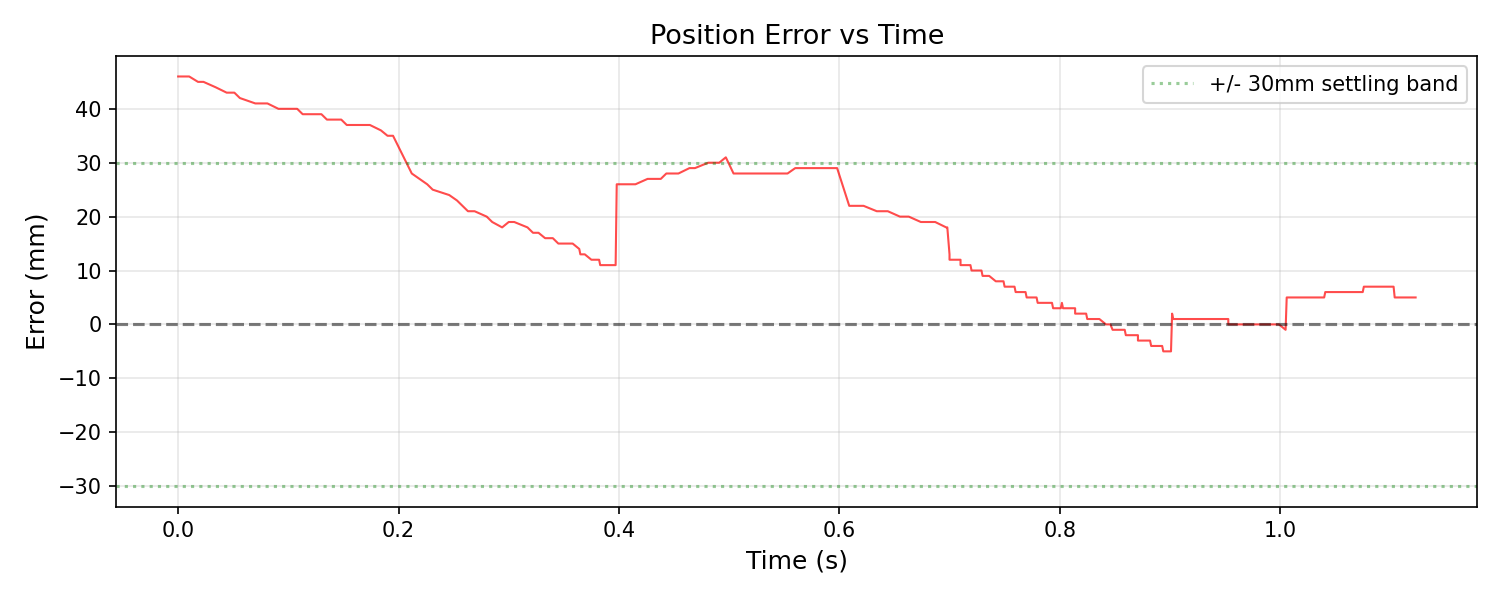
Position error over time. Settles within ±30mm band in about 0.5s.
Max speed from ToF data was about 110 mm/s, average approach speed around 70 mm/s.
Trial from 2000mm:
Close range with perturbation:
Perturbation test:
The controller recovers from perturbations. Push it toward the wall and it backs up, pull it away and it drives forward.
Different surface / diagonal approach:
Extrapolation
The ToF only gives new data at ~11 Hz but the PID loop runs at ~388 Hz. Instead of using stale data for 36 loops I extrapolate from the last two readings.
// On new reading: compute slope
tof_slope = (tof_current - tof_prev) / (tof_current_time - tof_prev_time);

// Every loop: estimate current distance
distance_est = tof_current + tof_slope * (millis() - tof_current_time);
In the ToF plot above the blue line smoothly fills in between the red dots instead of being a staircase. I also put a low-pass filter on the derivative (alpha=0.05) to keep it from spiking on noisy readings.
| Component | Rate |
|---|---|
| ToF sensor | ~11 Hz |
| PID loop | ~388 Hz |
| Ratio | ~36x |