Lab 4 - Motor Drivers and Open Loop Control
Posted on 2026-03-11
1. Prelab
Wiring Diagram
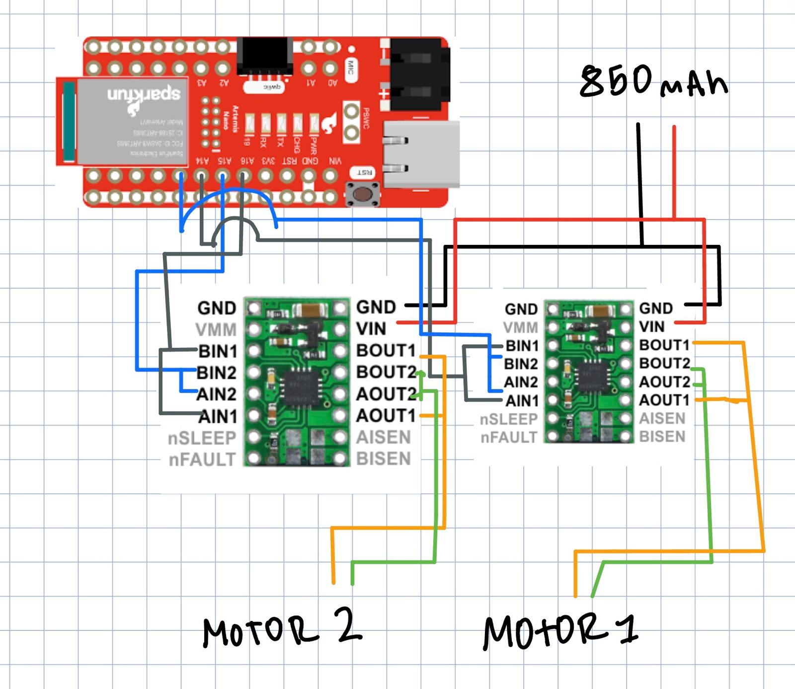
I used two DRV8833 dual motor drivers with the two channels on each chip parallel-coupled (AIN1↔BIN1, AIN2↔BIN2, AOUT1↔BOUT1, AOUT2↔BOUT2) to deliver double the current to each motor. The Artemis controls each driver with two PWM pins:
| Pin | Function | Motor Driver |
|---|---|---|
| 14 | LEFT_FWD (AIN1+BIN1) | Driver 1 |
| 13 | LEFT_BWD (AIN2+BIN2) | Driver 1 |
| 16 | RIGHT_FWD (AIN1+BIN1) | Driver 2 |
| 15 | RIGHT_BWD (AIN2+BIN2) | Driver 2 |
I picked these pins because they all support PWM and are physically close together on the Artemis Nano, which keeps signal wires short inside the chassis.
Battery Discussion
The motors and the Artemis are powered from separate batteries. The 850mAh Li-Ion powers both motor drivers, while a separate 650mAh battery powers the Artemis. This is important because the motors draw large, spiky currents especially during direction changes or stalls, and sharing a single battery would cause voltage drops and EMI noise that could crash the microcontroller or mess up BLE and sensor readings.
Lab Tasks
Power Supply and Oscilloscope Setup
I connected the first motor driver to the external power supply set at 3.7V with a 2A current limit (matching the 850mAh battery specs). I quickly verified the PWM output on both motor drivers with the battery power.
#define LEFT_FWD 14
#define LEFT_BWD 13
#define RIGHT_FWD 16
#define RIGHT_BWD 15

pinMode(LEFT_FWD, OUTPUT);
pinMode(LEFT_BWD, OUTPUT);
pinMode(RIGHT_FWD, OUTPUT);
pinMode(RIGHT_BWD, OUTPUT);

// Forward at ~59% duty cycle
analogWrite(LEFT_FWD, 150);
analogWrite(LEFT_BWD, 0);
delay(3000);

// Stop
analogWrite(LEFT_FWD, 0);
analogWrite(LEFT_BWD, 0);
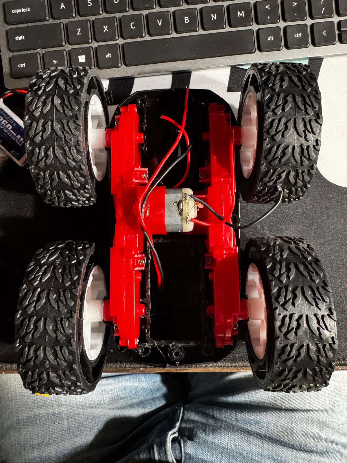
Car Disassembly
I took apart the RC car, removed the blue shell, cut the LED wires, and disconnected the factory control PCB by cutting the motor and battery wires as close to the board as possible to keep maximum wire length on the motors.
Soldering Motor Drivers to Motors
I soldered the motor wires to each DRV8833’s parallel-coupled output pins. Used stranded wire and kept everything short to reduce EMI noise and fit inside the chassis.
Single Motor Test (Battery Powered)
After wiring the first motor driver, I switched from the external power supply to the 850mAh battery and tested spinning the motor forward and backward. The car was on its side so the wheels were in the air.
Open video if it doesn't play above.
Both Motors Test (Battery Powered)
Wired the second motor driver and tested both motors spinning forward and backward together. Both sets of wheels spin as expected.
Open video if it doesn't play above.
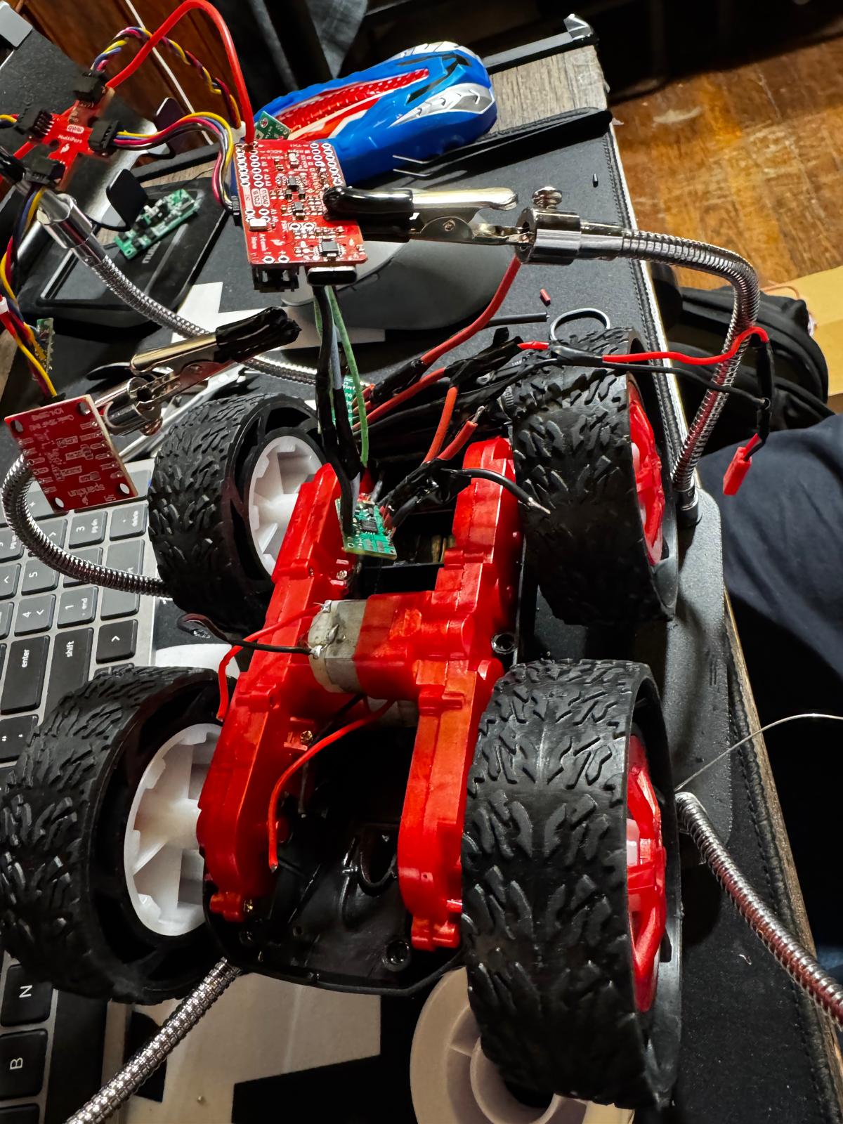
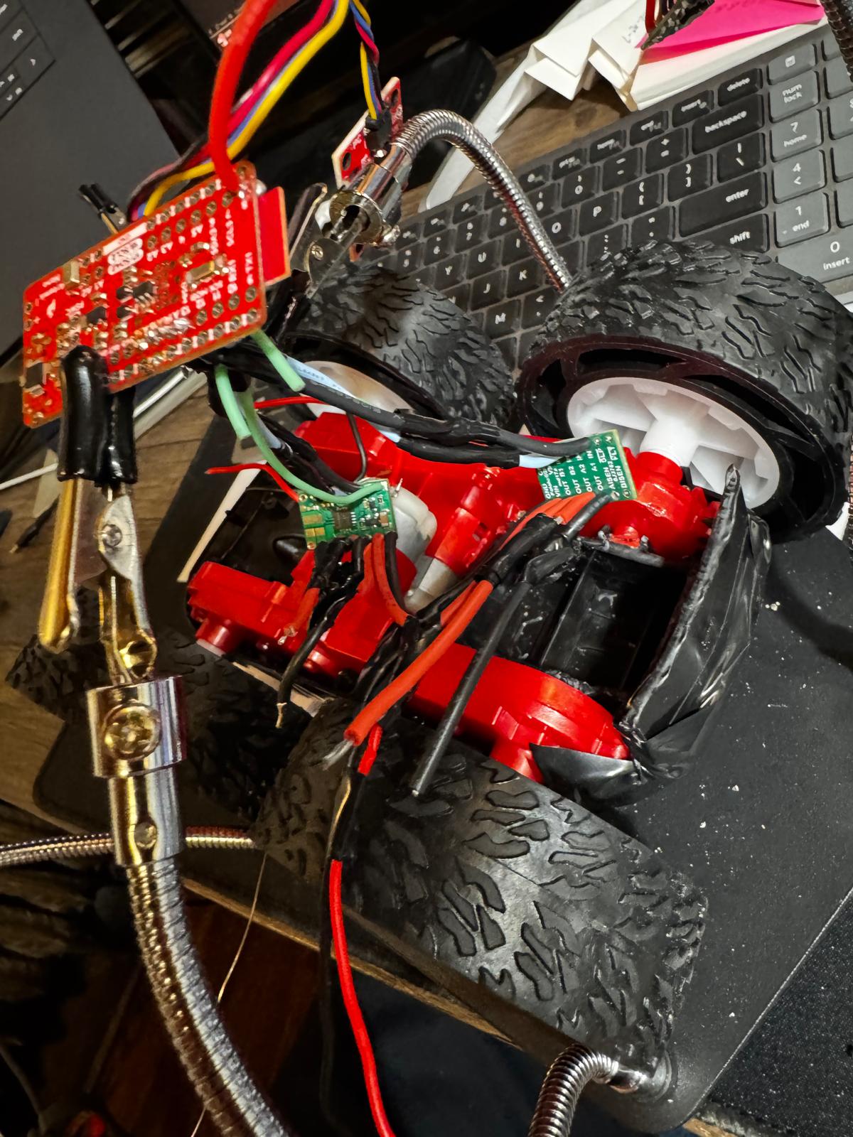
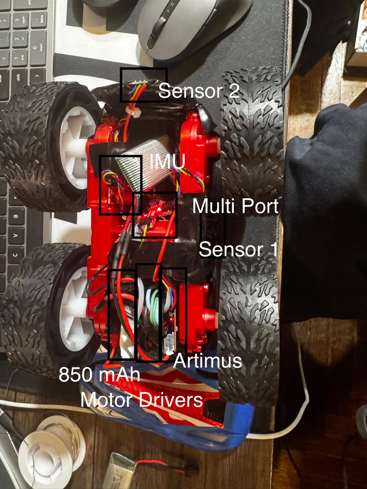
Component Placement
I installed the Artemis, both motor drivers, IMU, ToF sensors, and batteries inside the chassis. Everything is secured so nothing sticks out past the wheels since the car flips during stunts. I also added BLE motor commands so I can control the car wirelessly from Jupyter.
BLE Motor Control
I added BLE commands for motor control so I could drive the car wirelessly from Jupyter. The drive() helper handles direction and applies a calibration factor to the left motor.
void drive(int left_speed, int right_speed) {
    int left_cal = constrain((int)(abs(left_speed) * motor_calibration), 0, 255);
    int right_val = constrain(abs(right_speed), 0, 255);

    if (left_speed > 0) {
        analogWrite(LEFT_FWD, left_cal);
        analogWrite(LEFT_BWD, 0);
    } else if (left_speed < 0) {
        analogWrite(LEFT_FWD, 0);
        analogWrite(LEFT_BWD, left_cal);
    } else {
        analogWrite(LEFT_FWD, 0);
        analogWrite(LEFT_BWD, 0);
    }

}
Quick test connecting via BLE and driving the car:
Open video if it doesn't play above.
Lower PWM Limit
I tested decreasing PWM values to find the minimum that gets the robot moving on the ground. Starting from rest, the robot needed around 60 PWM on both sides to move forward. For on-axis turns (one motor forward, one backward), it needed around 70 PWM. The robot requires slightly more power to overcome static friction from rest vs keeping it moving once it’s already going.
# Testing forward lower limit from Jupyter
pwm_test = 60
ble.send_command(CMD.SET_MOTORS, f"{pwm_test}|{pwm_test}")
time.sleep(3)
ble.send_command(CMD.STOP_MOTORS, "")
Calibration
My motors didn’t spin at the same rate at equal PWM, so the car would drift to one side. I implemented a calibration factor that scales the left motor’s PWM. After some testing I found a calibration factor that got the car to drive reasonably straight over 2m along a tape line on the floor.
# calibration factor via BLE
ble.send_command(CMD.SET_CALIBRATION, "7.0")

# Straight-line test
ble.send_command(CMD.SET_MOTORS, "120|120")
time.sleep(4)
ble.send_command(CMD.STOP_MOTORS, "")
Open video if it doesn't play above.
Open Loop Control
For the open loop demo I programmed a sequence of forward movements and turns, all triggered wirelessly via BLE. The car drove in loops around a point, showing untethered open loop control. Time-based commands made the turns somewhat inconsistent which is expected without sensor feedback.
# Open loop demo — 3 loops
ble.send_command(CMD.SET_MOTORS, "150|150")
time.sleep(1.5)
ble.send_command(CMD.SET_MOTORS, "-120|120")
time.sleep(0.5)
ble.send_command(CMD.SET_MOTORS, "150|150")
time.sleep(1.5)
ble.send_command(CMD.SET_MOTORS, "120|-120")
time.sleep(0.5)
ble.send_command(CMD.SET_MOTORS, "150|150")
time.sleep(1.0)
ble.send_command(CMD.STOP_MOTORS, "")
Open video if it doesn't play above.