Lab 3 - ToF
Posted on 2026-03-03
1. Prelab
I2C Sensor Address
The VL53L1X datasheet lists the default I2C address as 0x52 (8-bit write address). But, the arduino uses 7-bit addressing, so the I2C scan reports 0x29. The IMU (ICM-20948) appears at 0x69.
Approach to Using 2 ToF Sensors
I chose the XSHUT pin method: at boot, I pulled XSHUT LOW on sensor 2 to shut it down, changed sensor 1’s I2C address from 0x52 to 0x54, then released XSHUT to bring sensor 2 back online at the default 0x52. This made it so both sensors have unique addresses and can be read independently. I decided to use this method instead of continuously toggling sensors on/off for each read, which wouldve given me a smaller sampling rate and add initialization latency.
// ToF dual-sensor init via XSHUT (pin 8)
pinMode(XSHUT_PIN, OUTPUT);
digitalWrite(XSHUT_PIN, LOW);   // shut down XSHUT sensor
delay(150);

// Init sensor 1 (non-XSHUT), change address to 0x54
if (distanceSensor1.begin() != 0) {
    // Address may already be 0x54 from previous run (persists across resets)
    distanceSensor1.setI2CAddress(0x54);
    distanceSensor1.begin();
} else {
    distanceSensor1.setI2CAddress(0x54);
}

digitalWrite(XSHUT_PIN, HIGH);  // bring sensor 2 back up
delay(150);
distanceSensor2.begin();         // sensor 2 at default 0x52
Sensor Placement and Missed Obstacles
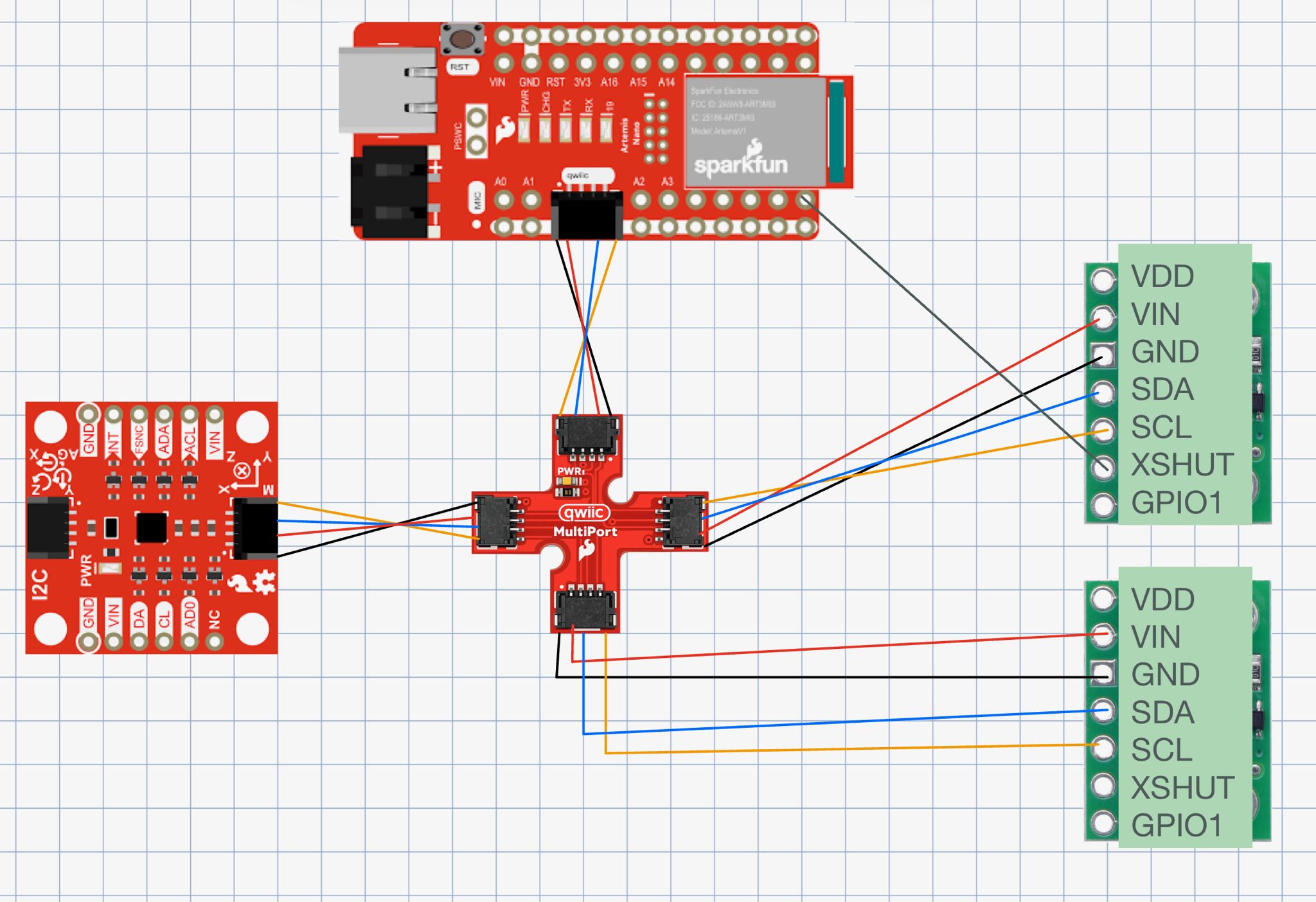
I plan to mount sensor 1 facing forward on the front of the chassis to detect obstacles ahead, and sensor 2 on one side for wall-following and detecting obstacles during turns. The robot will miss obstacles approaching from behind, from the uncovered side, objects below the beam height, and thin objects that fall between the sensor’s field of view. I used long QWIIC cables for both sensors since they mount on the chassis edges, while the IMU stays near the Artemis with a short cable.
Lab Tasks
Battery Power + Soldering
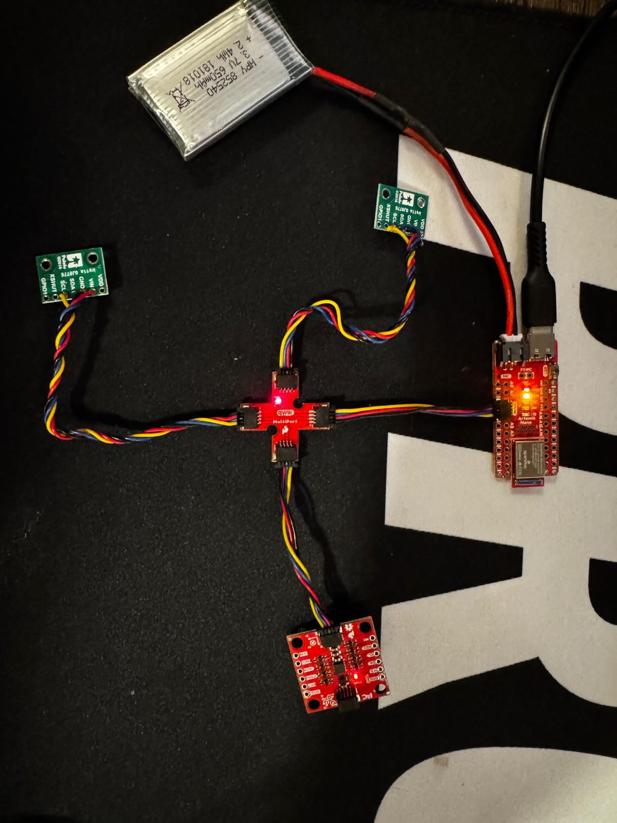
I soldered the JST connector to the 650mAh LiPo battery (cutting wires one at a time to avoid shorting), applied heat shrink, and verified polarity. The Artemis powers on via battery and communicates over BLE untethered I confirmed with a PING/PONG test from Jupyter.
I2C Scan
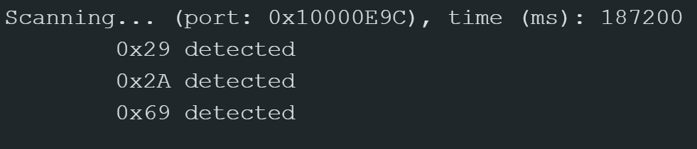
Ran the Apollo3 Example05_Wire_I2C scanner after the dual-sensor init. The scan found three devices:
- 0x29 — VL53L1X ToF sensor 2 (XSHUT sensor, default address 0x52 = 0x29 in 7-bit)
- 0x2A — VL53L1X ToF sensor 1 (address changed to 0x54 = 0x2A in 7-bit)
- 0x69 — ICM-20948 IMU (with AD0_VAL = 1)
Distance Mode
The VL53L1X has three ranging modes:
- Short (1.3 m max) - fastest, most accurate at close range
- Medium (3 m max)
- Long (4 m, max) - slower at ~100ms, more susceptible to ambient light
I chose Short mode because for obstacle avoidance the robot needs accurate close-range detection more than long range. Short mode is faster (~30ms vs ~100ms) and less susceptible to ambient light noise, which matters for quick reactions. I tested accuracy by placing a flat object at a known distance (~180mm measured with a ruler) and both sensors read consistently within a few mm of the actual value.
Open video if it doesn't play above.
Two ToF Sensors + IMU
Both ToF sensors and the IMU work together on the shared I2C bus. After the XSHUT init sequence, sensor 1 is at 0x54 (0x2A) and sensor 2 is at 0x52 (0x29), so they can be read independently. One gotcha I ran into is that the ToF sensors in continuous ranging mode hog the I2C bus, so I have to stop both sensors’ ranging before collecting IMU data and restart them after. The checkForDataReady() approach keeps the main loop non-blocking so neither sensor stalls the other.
Speed Test Discussion
Looking at the serial output, the main loop executes in approximately 1-2 ms per iteration. ToF data only appears every ~43 ms when a sensor has new data available (Short mode timing). The limiting factor is the ToF sensor’s ranging time, not the loop speed. I used checkForDataReady() instead of a blocking read which made sure the loop didn’t hang.
// Non-blocking dual ToF read in loop
if (distanceSensor1.checkForDataReady()) {
    tof_data1[tof_index] = distanceSensor1.getDistance();
    distanceSensor1.clearInterrupt();
}
if (distanceSensor2.checkForDataReady()) {
    tof_data2[tof_index] = distanceSensor2.getDistance();
    distanceSensor2.clearInterrupt();
}
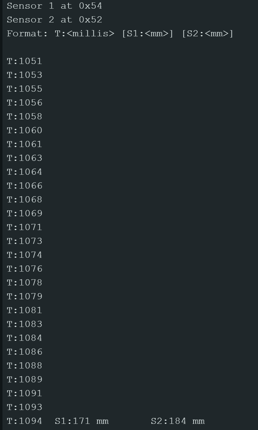
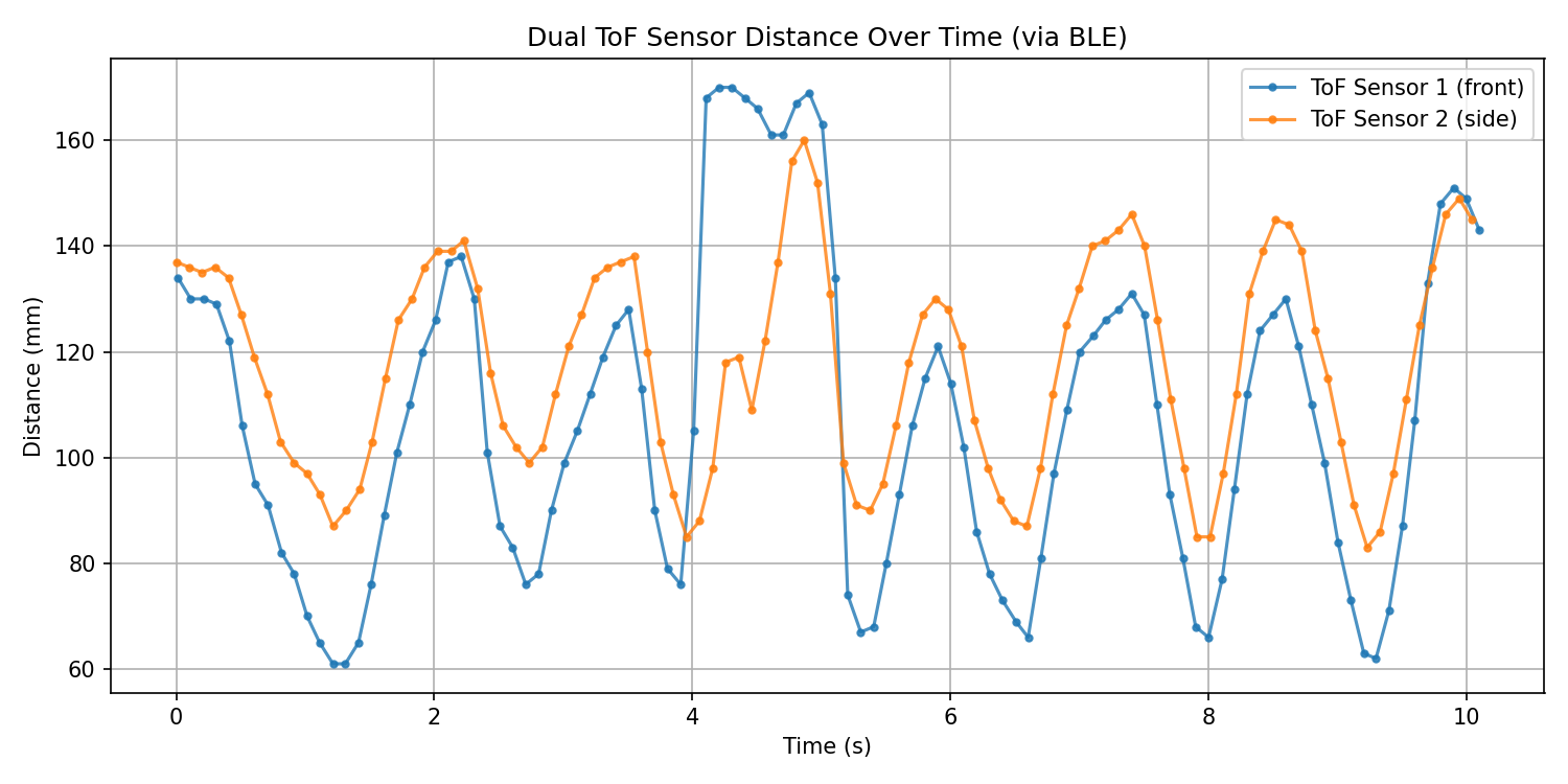
ToF Distance vs Time
I collected dual ToF data for 10 seconds on the Artimus using a non-blocking flag based approach (which is the same I used in lab 2). Basically I stored both sensors’ readings using arrays then sent them over BLE to jupyter for plotting. Below is the code:
if (tof_collecting && tof_index < TOF_ARRAY_SIZE) {
    bool s1_ready = distanceSensor1.checkForDataReady();
    bool s2_ready = distanceSensor2.checkForDataReady();
    if (s1_ready || s2_ready) {
        tof_time[tof_index] = millis();
        tof_data1[tof_index] = s1_ready ? distanceSensor1.getDistance() : -1;
        tof_data2[tof_index] = s2_ready ? distanceSensor2.getDistance() : -1;
        if (s1_ready) distanceSensor1.clearInterrupt();
        if (s2_ready) distanceSensor2.clearInterrupt();
        tof_index++;
    }
}
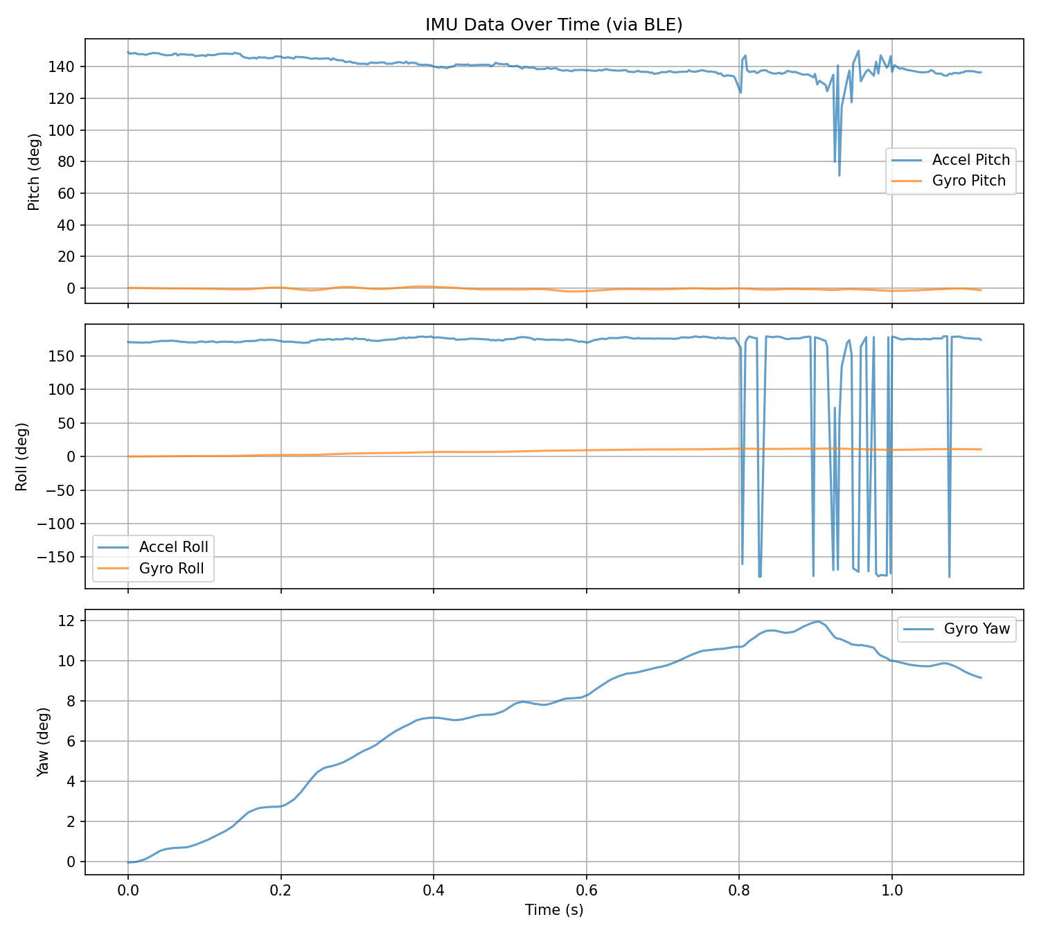
IMU Angle vs Time
I collected the IMU data while tilting/rotating the board, then sent over BLE. The plot shows accelerometer pitch/roll and gyroscope-integrated pitch/roll/yaw. The gyro yaw shows drift over time (expected without complementary filter correction), while accelerometer values remain bounded and reflect actual tilt. I temporarily paused both ToF sensors’ ranging during IMU collection to prevent I2C bus contention.